


Turmoil in the sky
11/02/2020

The environmental impact of aircraft carbon footprint is of rising importance to all operators as consumer demand for air travel continues to grow. The aviation industry holds a small contribution to global emissions, but unequivocally, it is one of the fastest growing contributors to emissions. Since the 1970s, when the price of aviation fuel began to spiral upward, airlines and aircraft manufacturers have explored many ways to reduce fuel consumption by improving the operating efficiency of their aircraft. Fuel economy concerns have been particularly important for operators of commercial aircraft, which typically fly many hours per day in competitive markets. Hence, there are also economic incentives for reducing emissions, since reduced emissions are naturally related to reduced fuel consumption and savings in fuel expenditure for air carriers. A great potential source for fuel savings is reducing parasitic drag of the airframe, such as inherent wingtip vortices.
Introduction to wingtip vortices
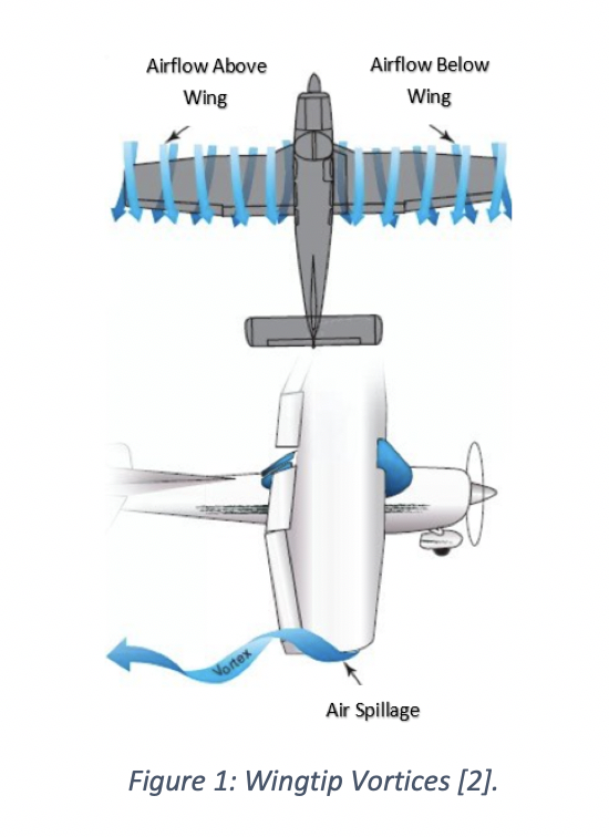
Wingtip vortices are schematically illustrated in Figure 1. If a wing is producing lift, a pressure differential will exist between the upper and lower surfaces, i.e. for positive lift, the static pressure on the upper surface will be less than on the lower surface. At the tips of the wing, the existence of this pressure differential creates a vortex where the high-pressure air below the wing can escape to the low-pressure area above the wing to form a swirling tunnel of turbulent air along (top of Figure 1) and behind the wing (bottom of Figure 1). The vortex is strongest when the angle of attack is high, such as during take-off and landing, because the pressure differential at high angles of attack is greatest during these phases.
Why are wingtip vortices detrimental to aircraft aerodynamics?
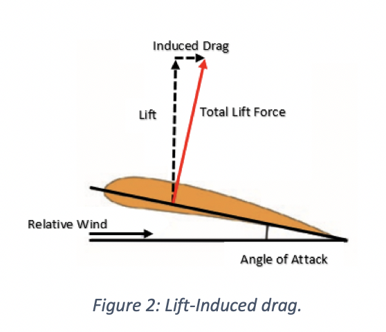
To create a specific lift coefficient with the airfoil section, a certain angle of attack must exist between the airfoil chord line and the relative wind (see Figure 2). However, as the total lift force is developed perpendicular to the wing chord line, it is angled slightly backwards. There are two problems occurring here; firstly, some of the total lift force is now deflected backwards leading to the creation of lift-induced drag (illustrated in Figure 2); and secondly, there is a smaller component of lift pointing upwards to counterbalance the weight of the aircraft. Both of these effects are to the detriment of the lift-to-drag ratio, a key efficiency parameter in aircraft design. Thus, as a result of this decrease in vertical lift, the wing must be given an angle of attack greater than the section angle in order to generate more lift to account for the inclination of the total lift force. However, any increase in the angle of attack also increases the lift-induced drag. Wingtip vortices exacerbate this lift-induced drag by causing the total lift force to point even further backward A number of possible solutions exist for mitigating the effect of vortex-induced drag but conventionally, wingtip retrofits, commonly known as winglets, are used to mitigate the problem.
How do winglets help to improve the situation and what are some of the drawbacks?
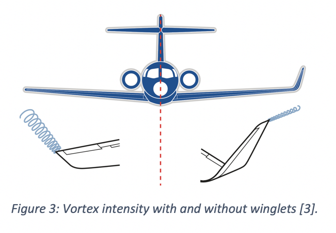
One of the visible actions taken by commercial airframe manufacturers to reduce wingtip vortices is the modification of an aircraft’s wingtip by installing, as shown in Figure 3, near-vertical “winglets”. Experience shows that these tip devices reduce block fuel consumption (total fuel burn from engine start at the beginning of a flight to engine shutdown at the end of the flight) of the modified aircraft by 3% – 5%, depending on trip length [1].
Winglets are airfoil-shaped structures that also produce lift but are orientated inwards towards the fuselage relative to the rest of the wing. The presence of winglets changes the effect that wingtip vortices have on lift and drag. The winglets cause the relative wind to bend inwards towards the fuselage, creating a forward vector of lift in the direction of flight counteracting some of the induced drag, as illustrated in Figure 4.
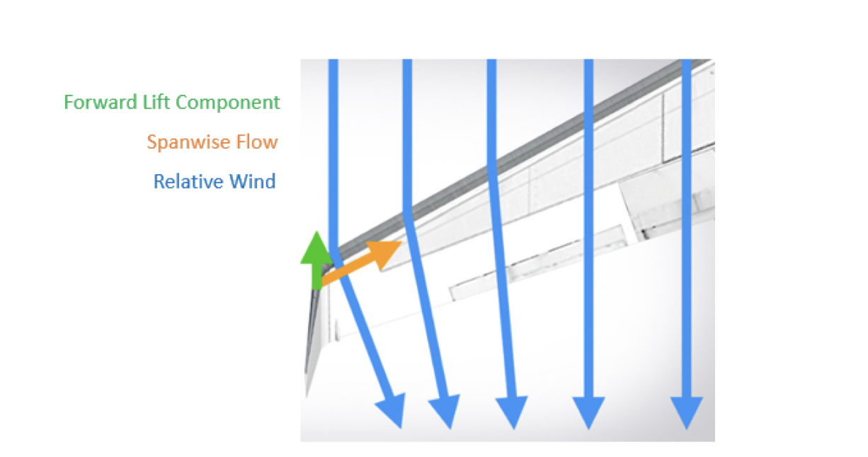
Figure 1: Creation of forward lift force to partially alleviate induced drag [4], however, winglets do not operate effectively under all conditions throughout the flight envelope and incur an added mass penalty. So, the question is whether winglets conserve more fuel by reducing drag than the extra fuel required to carry their mass. An inherent problem with winglets is their susceptibility to flutter and increased bending stresses in the winglet fold area. In fact, under some flight conditions an equal area, flat span extension can be a more effective and less risky design solution. Lastly, winglets are always present in flight, as they are fixed devices attached to the tips of wings, and because they are fixed surfaces, they provide their best lift-induced drag reduction for a single design point. Hence, a more on-demand and active, rather than passive, type of control device could be of benefit. One example is the use of a “fluidic winglet”.
What is a fluidic winglet and how do they work?
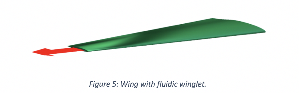
A fluidic winglet is a system architecture that can provide a controlled stream of air ejected outwards in the vicinity of the wingtip, as shown in Figure 5, to create an aerodynamic force strong enough to disrupt the vortex formation. This system architecture could potentially produce the same benefits as a winglet without a visible increase in wingspan.
The pressurized air for the fluidic winglet could be taken from:
- The jet engine
- The aircraft surface
- The leading edge of the wing
- An internal pressurised air tank
RAM drag (a common source of system-induced drag caused by taking in air, typically for cooling purposes) and weight penalties introduced from the above systems must be considered when evaluating the system. If air is taken from the aircraft surface, then a Laminar Flow Control (LFC), a Hybrid Laminar Flow Control (HLFC) system, or a duct located at the wing leading edge stagnation pressure line could be appropriate. However, this would not result in high jet momenta and will be limited to lower mass flow rates [5]. The LFC and HLFC systems are active boundary layer control techniques, shown in Figure 6, that help to maintain the laminar flow state by means of suction onto the wing surface during flow states that would otherwise be transitional or turbulent.
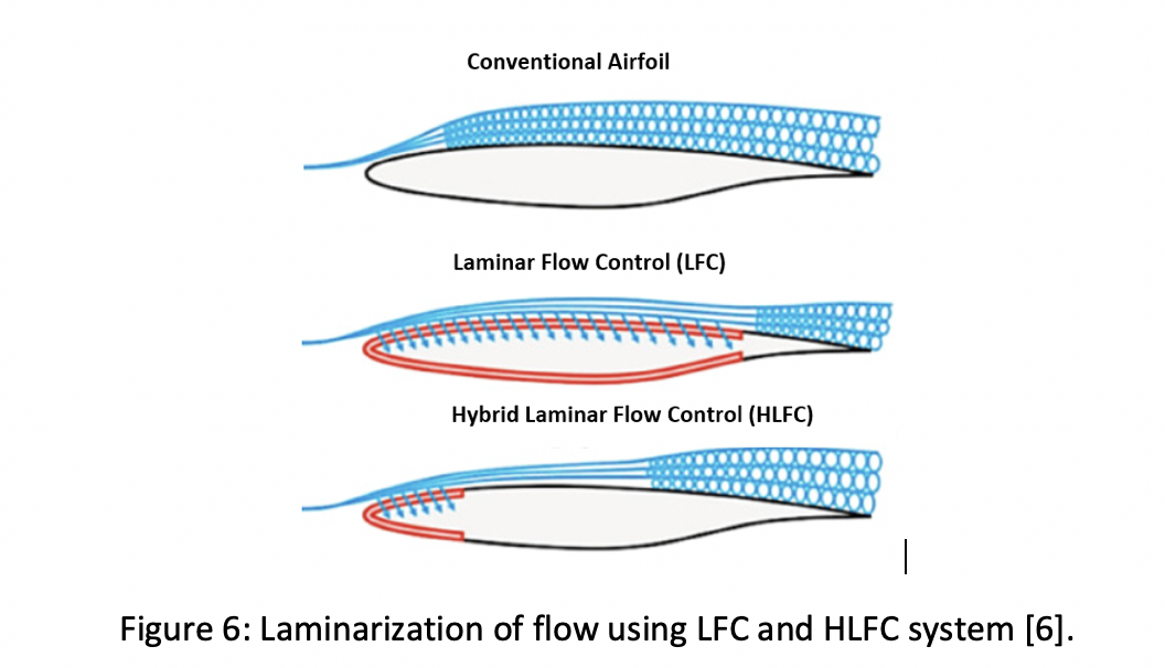
Figure 1: Laminarization of flow using LFC and HLFC system [6].
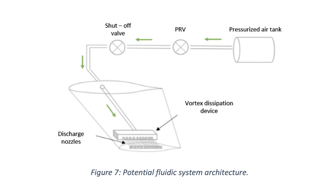
If the air used to operate the fluidic winglet is taken from a separate pressurised tank inside the fuselage, the fluidic system could look something like depicted in Figure 7. Once the pilot signal is received, a solenoid valve allows the air to be released from the tank where it is regulated to provide the required exit velocity. The air then flows into the vortex dissipation device where the air is distributed to the discharge nozzles. If the exit pressure past the pressure regulating valve (PRV) exceeds the design limit, a shut-off valve ahead of the PRV will not allow fluid to pass above a certain set pressure as a fail-safe.
Analysis – What potential benefits of the fluidic winglet can be deduced over conventional alternatives?
In order to deduce the potential benefits of the fluidic winglet, the lift coefficient (CL), drag coefficient (CD) and lift-to-drag ratio (CL/CD) of three models are investigated using ANSYS Fluent, and the results are extracted and summarised in Figure 8. The models designed are:
- A clean wing (CW) with no winglet attached: designed from a NASA HSNLF (1)-0213 airfoil with a leading-edge sweep angle of 33° and a taper ratio of 0.4.
- A wing with a raked winglet (WRW): designed from a NACA 0012 airfoil with 10% of wing semi-span and a taper ratio of 0.2 and with a sweep angle greater than that of the wing of about 57°.
- A wing with the fluidic winglet (WFW): this will not require a wingtip extension and hence, there is no physical increase in the wing’s span. The fluidic winglet instead consists of a rectangular high-aspect ratio slot.
Note: The models do not have an aerodynamic twist consideration.
The boundary conditions that constitute the flow variables are: a freestream velocity of 50 m/s and an injection velocity three times the freestream (150 m/s) with a jet sweep angle equivalent to that of the wing sweep (i.e. the jet is colinear with the wing). These models will be tested at high angles of attack of 7.5°, 10° and 12.5° to simulate the effect of the fluidic winglet on the vortex when it is strongest.
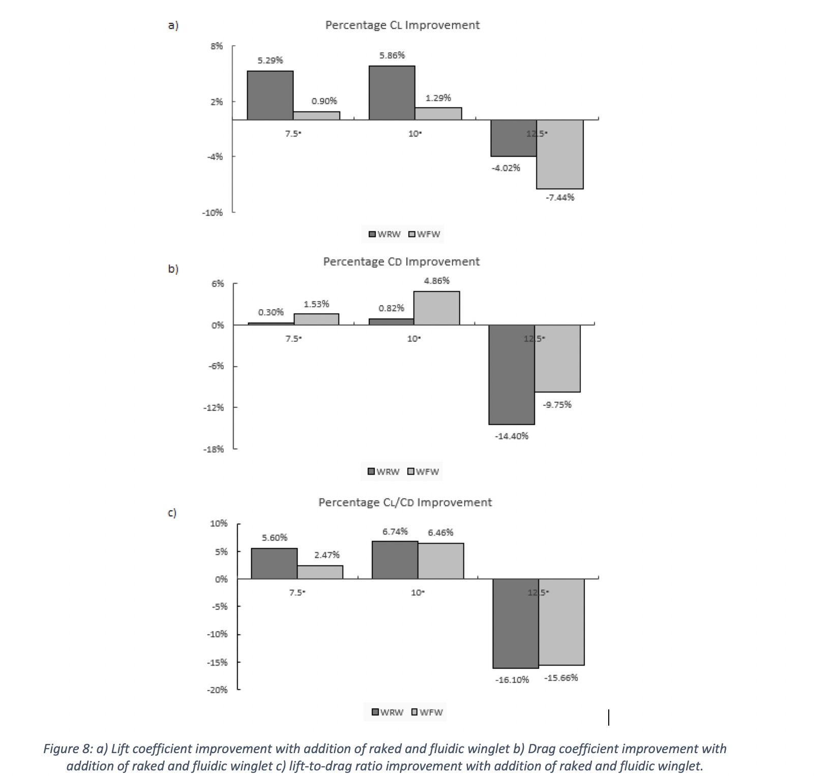
As illustrated in Figure 8c), the results indicate that having a tapered wingtip extension (i.e. a raked wingtip, WRW) provides an improved aerodynamic efficiency (CL/CD) of 7% for an angle of attack of 10°, and generally better levels of drag reduction are expected at low angles of attack. As shown in Figure 8a), the WRW improves the lift coefficient much more than the fluidic wingtip (WFW). This is due to the increase in wing area added by the physical wingtip. However, this additional surface area causes a parasitic component of drag, which is why the WFW outperforms the WRW design in terms of drag coefficient, see Figure 8b). Further, in Figure 8c) it appears that the WRW’s performance is reduced by 16% at an angle of attack of 12.5°, which occurs due to local wingtip stall. There are two reasons for this occurrence; firstly, the dissimilarity between the main wing airfoil and the raked winglet airfoil and secondly, the WRW is not twisted. The WRW should employ twist to avoid local stalling at such high angles of attack.
Similarly, the application of the WFW at high angles of attack leads to improvements to the wing’s aerodynamic efficiency. As shown in Figure 8c), at 7.5° angle of attack, the lift-to-drag ratio is increased by 2.5%, and at 10°, the lift-to-drag ratio is increased by 6.5%. However, for the 12.5° angle of attack, when the 50 m/s freestream air collides with the 150 m/s jet, stalling occurs locally, thus spoiling the lift and increasing drag. The stall occurs due to a local increase in the Reynolds number in the region where the freestream and jet efflux meet.
Nonetheless, because the fluidic winglet has no additional surface exposed, there is no increase in parasitic drag. This fact contributes to acceptable drag reductions as shown in Figure 8b). Hence, the overall enhancement of the lift-to-drag ratio between the WRW and the WFW is very similar emphasizing the capability of the WFW. Even though the WRW is more effective at improving the lift, the WFW is better at reducing drag without compromising lift; can be activated at a specific angle of attack; and has the potential to deliver better levels of drag reduction at more than a single design point during the flight envelope. Other benefits not only include potential improved fuel economy but also improved payload-range capability, improved take-off performance, and less take-off noise.
How is the fluidic winglet able to improve the lift-to-drag ratio?
The WFW is able to improve aerodynamic efficiency by altering the chordwise lift distribution along the wingspan. It is observed that, at high angles of attack, the sectional chordwise pressure distribution on the upper and lower surface of the WFW changes favourably from root to tip. This can be seen more clearly using Figure 9 where the sectional lift force on discrete sections along the wing is estimated using Equation 1, where PL is the wing’s lower surface pressure, PU is the pressure on the wing’s upper surface and S is the wing area.
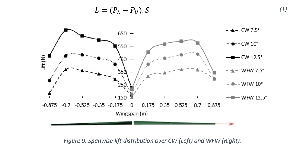
The spanwise variation in the sectional lift force, as shown in Figure 9, for the CW is observed to increase until the 80% wing semi-span location, at which point it drops off dramatically. This drop off in lift force towards the wingtip (100% wing semi-span position) is due to the creation of wingtip vortices that disrupt effective lift generation over the wing. It is clear that the aerodynamic lift force is considerably increased by the WFW towards the wingtip for the 7.5° and 10° conditions, thereby demonstrating the effectiveness of the jet efflux to increase the aerodynamic loading at the wingtips for the angles of attack tested herein. The only exception is the 12.5° angle of attack condition where the addition of the efflux creates a local stall condition, as previously discussed
Additional thoughts – How could fluidic winglets be implemented?
It is important to evaluate aircraft inventory and identify the most suitable aircraft candidates for fluidic winglet modification. The process could be summarised under four main tasks:
- Examine the feasibility of modifying aircraft with fluidic winglets, to include a cost-effectiveness analysis of the modification in net present value (NPV) terms.
- Determine the market price of aviation fuel at which incorporating the fluidic winglets would be beneficial for each platform.
- Consider impact to aircraft maintenance and flight operations (including ground operations).
- Investment strategies to minimize the operator’s capital investment and maximize investment return.
These tasks call for a quantitative assessment of the costs and benefits of fluidic winglet modifications on a variety of platforms. In a comprehensive analysis, one would need to include the non-recurring engineering costs of wing analysis and fluidic system design, as well as the costs of materials, manpower, and out-of-service time to accomplish the modification, financial implications, training costs, potential impacts on maintenance docks, costs associated with software and technical manual revisions, and any impacts on maintenance, operations, or mission accomplishment.
In each case, the aircraft structure needs to be studied and determined to be appropriate; engineering design must be analysed in detail; modifications will need to be prototyped, tested, and certified; modification kits to be developed and flight manuals revised as required. Past commercial experience with aircraft that have installed conventional winglets has shown that there have been no significant impacts on aircraft maintenance, flight operations, or ground operations (gate space, taxiways, hangars, etc.) [1].
Conclusion
It is clear that aerodynamic improvements, including fluidic winglets, can make significant contributions to the efficiency of aircraft. In each case, however, the appropriateness of such structural/system modifications must be determined fleet by fleet. These decisions are very complex and will depend on many factors, including the design of the aircraft’s structures, systems design, design margin within those structures, the condition of the structures, mission profiles, utilization rates, fuel consumption rates, fuel prices, and the remaining life of the aircraft. There are also other ways to reduce fuel consumption, many of which have already been adopted by commercial airlines. Nonetheless, the best solution is decided by economics rather than aerodynamics.
The design of the fluidic winglet combines several disciplines such as structures, manufacturing and assembly, systems, aerodynamic and flight dynamics. The selection of the most appropriate system air resource and subsequent system design will depend upon the jet efflux requirements of the fluidic winglet. The benefits of the concept are highly dependent upon the jet parameters like the jet momentum coefficient, jet dihedral, jet sweep, jet thickness and jet area as well as the boundary conditions. Higher jet momenta and smaller jet cross-sectional areas show promise to move the vortex centre further away from the wingtip to increase the effective wingspan. Jet sweep angles higher than the wing sweep angle are not suspected to provide improved results.
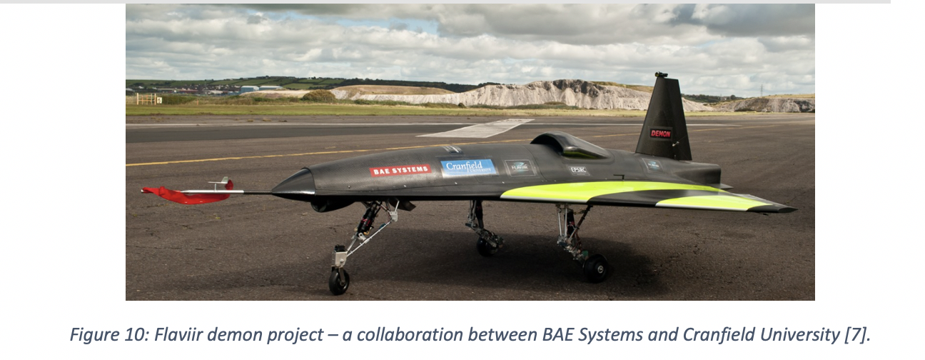
Since 2010, BAE Systems has set out to develop key technologies and skills with long-term collaboration from academia, industry and the UK government to create the combat air system of the future so that the UK can deliver more advanced capabilities through shared investment and revolutionise aircraft design. The first ever exhibit of fluidic flight control (i.e. no flaps, elevators or ailerons) begins with the FLAVIIR Demon Project (Flapless Air Vehicle Integrated Industrial Research program), a UAV showcasing new technology for the conventional flight control system. There are slots located on the wing’s trailing edge for the blown compressed air taken from the APU (Auxiliary Power Unit) to be curled either upwards (i.e. lowering the wing) or downwards (i.e. lifting the wing) to provide for control of the aircraft. This allows for a more seamlessly integrated design with fewer mechanically moving parts, and hence, a design with reduced edges and gaps that make the aircraft less observable on radar.
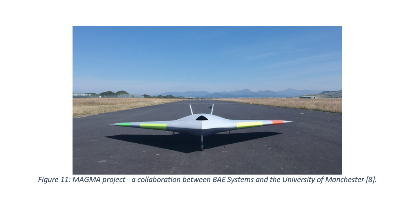
Similarly in 2017, BAE Systems, in collaboration with the University of Manchester, revealed the first flight of MAGMA, a new UAV iteration showcasing novel control technologies for wing circulation control and fluidic thrust vectoring. The wing circulation control system takes air from the aircraft engine and blows it supersonically through the trailing edge of the wing to provide roll control for the aircraft. The fluidic thrust vectoring systems also uses blown air to deflect the main thrust allowing for the pitch direction of the aircraft to be changed. So far, flight tests have been promising and we are awaiting the first use of such circulation control in flight on gas turbine aircraft.
References
[1]National Research Council. ASSESSMENT OF WINGTIP MODIFICATIONS TO INCREASE THE FUEL EFFICIENCY OF AIRCRAFT, accessed 10/01/2020 [2] Jeffrey (2008). Wingtip Vortices and Wake Turbulence Explained, accessed 10/01/2020 [3] Mike C (2017). WHAT AM I: WINGLETS, accessed 10/01/2020 [4] Colin C (2019). This Is How Winglets Work, accessed 10/01/2020[5] Ronald J (1998). Overview of Laminar Flow Control, NASA Technical Paper, accessed 10/01/2020
[6] Krishnan K (2017). Review of hybrid laminar flow control systems, accessed 10/01/2020 [7] Ben C (2010). DEMON UAV achieves historic first ‘flapless flight’, accessed 10/01/2020 [8] Andrea K (2019). MAGMA: The future of flight, BAE Systems, accessed 10/01/2020Categories & Tags:
Leave a comment on this post:
You might also like…

From national service to Environmental Engineering: My journey to Cranfield
Postgraduate study is often a defining step in shaping one’s academic and professional direction. For me, pursuing an MSc in Environmental Engineering at Cranfield University has been both a personal and professional adventure—one that ...

From limited experience to a UK marketing career
Top tips for postgraduate marketing students by Elnaz Dashchi, Strategic Marketing MSc alumni Coming into the postgraduate Strategic Marketing MSc, I did not have a lot of professional experience - and that made me ...

My journey to Cranfield as an FIA Motorsport Engineering Scholar
"You don’t need to fit a stereotype to succeed in engineering or motorsport. You need curiosity. Resilience. And the confidence to take up space." In this blog, Sanya Jain, current MSc student and FIA ...

‘Getting started with Bloomberg’ training – discover the power of Bloomberg terminals
Perhaps you've heard people talking about Bloomberg or heard it mentioned in the news and are wondering what all the fuss is about? Why not come along and find out at our Getting started with ...

Commonwealth Scholarships play a critical role in developing sustainability and leadership in Africa
Q&A with Evah Mosetlhane, Sustainability MSc, Commonwealth Distance Learning Scholar What inspired you to pursue the Sustainability MSc at Cranfield? I was inspired to pursue the Sustainability MSc at Cranfield because of the university’s ...

How do I reference a thesis… in the NLM style?
You may be including theses within your research. When you do so you need to treat them in the same way as content taken from any other source, by providing both a citation and a ...